High Voltage Transformer Wiring Diagram
Y Star Y Star Three Phase Transformer Phasor Diagram. Hvdt series high voltage distribution transformers wiring diagram line connection voltage jumper connection load connection voltage jumper connection wiring diagram line connection voltage jumper connection wiring diagram load connection x1 x2 x0 x3 neutral x1 x2 h1 h2 x3 h3 wiring diagram 1.
 How To Find The Primary And The Secondary Coils Of A Flyback Transformer Primary Secondary Transformers
This creates both a split-phase single phase supply and three-phase.

High voltage transformer wiring diagram. Encountered while drilling holes installing wiring etc during installation. Microwave Oven Transformer High Voltage Rig. Use a safety stick made of non-conductive material to draw the arc.
Connect X3 and X1 together 3. Connect X4 and X2 together 2. It is called orange leg because the wire is color-coded orange.
The connection diagram on the left shows how a deltadelta connection can be made either with three single-phase transformers or with one three-phase transformer. It is used when both single and three-phase power is desired to be supplied from a three phase transformer. This variac has 5 connections for wires.
Connect High Voltage L1 to X4 X2 4. The energy produced in generating plant is at low voltage and high current values. Figure 2a and b shows the plan and elevation drawings for a typical layout of two 115-kV bays one for a transmission line and the other for the HV side of a local transformer connected to a single 115-kV busbar.
Then insert the wire lug over the uncoated copper wire and then crimp the connection gadget permanently to the wire. The videos should give you good idea of the final product Im using only one of the 2 transformers. 150-200-300 5A S 2 1505A S 3 2005A S 4 3005A.
Balanced connection when supplying 1-φ and 3-φ loads. One disadvantage of delta connected three phase transformers is that each transformer must be wound for the full-line voltage in our example above 100V and for. The circuit diagram of the capacitor potential transformer is shown in the figure below.
Your high voltage will come out of a single terminal on the MOT. H1 x1 x3 x2 x4 h2. Transformer wiring diagram for single ratio current transformer.
If the losses in the network are neglected equation. The equivalent single-line diagram is depicted in Figure 2c. Connect H3 and H2 together 6.
A POWERSTAT Variable Transformer is a precision product packed with care. Multi ratio current transformer with an intermediate tapping on secondary winding. Graded High voltage insulation.
Two voltage levels available. The inductor is shaped like a doughnut toroid with wire wrapped radially This diagram has 5 terminals but 3 and 4 terminal variacs eliminate one or two of. Advantages of Y-Y Connection.
But before we continue dont hold the bare wire with your hand. To properly read a wiring diagram one provides to know how the particular components in the program operate. The stack of high voltage capacitor from the potential divider the capacitors of two sections become C 1 and C 2 and the Z is the burden.
Use a voltmeter to check voltage. This one has a primary winding three center-tapped filament windings and a center-tapped high-voltage winding. The inductor is shaped like a doughnut toroid with wire wrapped radially through Unlike a transformer with isolated input and output windings variacs have a single In the diagram to the left Ive stretched out the toroid.
In essence electrical substations consist of power transformers circuit breakers and secondary systems for protection load control and metering. In the tables and diagrams are for motor driven units and units with the knob. For my first Instructable I decided to make a high voltage power supply out of 2 microwaves.
The output of the transformer decreases proportionally with the ratio. The voltage applied to the primary of the intermediate transformer is usually of the order 10kV. Wye delta delta wiring diagram 2.
By convention the high leg is usually set. 1 3 I L of the line current where I L is the line current. DO NOT SERVICE WHILE ENERGIZED.
As you can see there are thirteen leads coming out of this transformer. Step 5-Terminate the high voltage side of the step-down transformer carefully. Connect High Low Voltage L2 to H1.
When the mains wiring is done ballast is hooked up etc now we are ready to draw an arc from the beastie. High-leg delta is a type of electrical service connection for three-phase electric power installations. The three-phase power is connected in the delta configuration and the center point of one phase is grounded.
The ground is the MOTs outer casing. Disadvantages of Y-Y Connection. Transformers change the voltage by a change in the ratio of wire turns on the primary to Typical wiring diagram for buck-boost use of Variac.
Below is a diagram of a typical power transformer. VOLTAGE TRANSFORMERS 121 The gross input in watts from a power circuit to a capacitance potential-device network is3 W 2πC1VSV2 sin αwatts 2 where power-system frequency. VS and V2 are volts defined as in Fig.
Depending on the generating plant type the GSU transformer has a nominal primary voltage value from 6 up to 20 kV. For instance when a module is usually powered up also it sends out a signal of fifty percent the voltage in addition to the technician does not know this he would think he offers an issue as he would expect the 12V signal. DIAGRAM C BUCK BOOST TRANSFORMERS Wiring Diagram WARNING.
α phase angle between VS and V2 C1 capacitance of main capacitor see Fig. Multi ratio current transformer with an intermediate tapping on primary winding. The voltage value produced in energy generation is increased and prepared for the long-distance energy transmission.
Presence of 3rd harmonic component in ungrounded Y-Y connection. In a delta connected Dd group of transformers the line voltage V L is equal to the supply voltage V L V SBut the current in each phase winding is given as. Variac Transformer Wiring Diagram.
Connect Low Voltage L1 to X1 X3 H4 5. The diagram gives the color code of the leads for each winding. The dashed lines indicate the transformer outlines.
The three single-phase transformer implementation can be seen by disregarding the outer dashed outline and the bushing labels shown at that outline and concentrating on the three smaller single-phase transformer outlines.
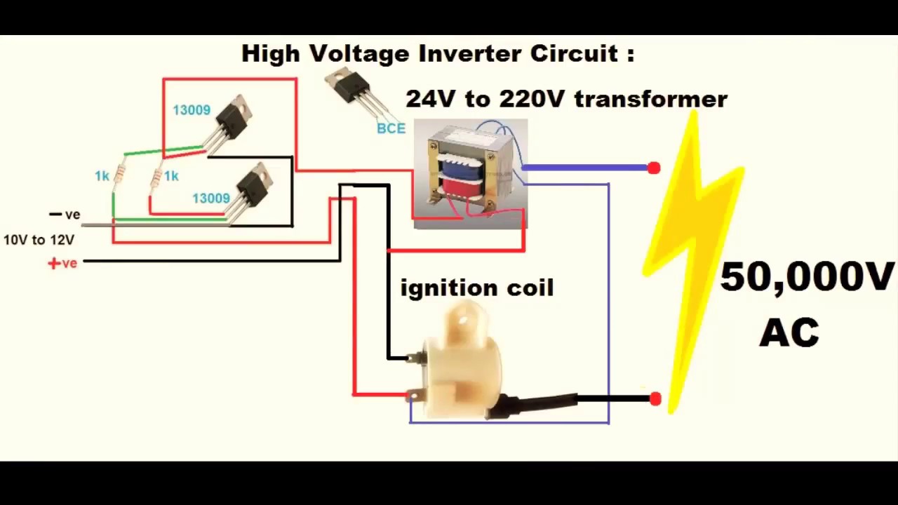
 9v To 13 5kv Inverter Circuit Circuit Diagram Power Supply Circuit Electronic Circuit Projects
 Typical High Voltage Transformer Diy Electronics Microwave Transformer Electrical Installation
 Basics Of Transformer Transformers Single Phase Transformer Step Down Transformer
 Pin On Electrical Symbols
 Pin On Faruk


